Clogged Canon print head

embguy

Printer Guru
Joined
Mar 9, 2009
Messages
331
Reaction score
3
Points
141
Jerry1111 said:
Trigger 37 said:
If anyone out there ever has this type of PH problem, I totally discourage you from even attempting to remove and replace the decoder chip on the back of the PH. This is Surface Mount Technology and the spacing of the solder pads are in the 7-10 mil range which is virtually impossible unless you have Surface mount desoldering and Wave soldering technology. You are just waisting you time. One of my first jobs in Senior Management at IBM was to fund and develop a Surface Mount manufacturering plant in Charlotte, NC. It took over $300 million to get it right. It was a lot of fun.
It must have been long time ago. Now everything (inlcuding BGAs) can be done on (almost) everyone's desk. A bit of patience, a lot of practice and good flux ;-)
As to the price of assembly line - electronics tend to get 50% cheaper every 2-3 years, so you can estimate how much it would be now - really not so much (probably because with ~$150m you've hit and solved a lot of problems which are not repeated any longer!).
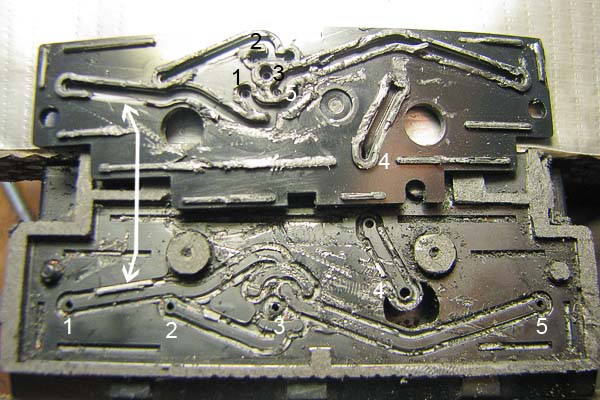
I'd be happy to resolder the chip, but my printhead is still printing.

Best Regards,

Jerry1111

PS: Don't want to start a flame. I'm just stating the facts ;-)
Here is an article on How-To: Make a surface mount soldering iron for $20 using part from Radio Shack and pet store

http://www.engadget.com/2006/03/07/how-to-make-a-surface-mount-soldering-iron

reflow-smd-test.JPG
 

Trigger 37

Printer Guru
Joined
Dec 23, 2006
Messages
607
Reaction score
4
Points
136
embguy,... Jerry1111,...Yes you are correct,... it has been many years since I did that job, in fact it was back in 1985. But this was not a little repair station to fix a defective card. This was a production line that could support the manufacture of 500,000 PC & Laptops a year. So it was a little more complex that what you are talking about.

However, I'm still laughing after looking at this article. Yes you found it on the internet. Yes it is clever. However it will never work. To remove a surface mount chip, such as the ones shown in the article, you have to heat all solder connects to the correct temperature at one instant and then you have to have a suction device to pull the IC off of the pad quickly. This home made air heater is clever, but it would never be able to heat all the pads at one time. Then you have to be able to DRESS THE SITE so the proper amount of solder is on each pad. To replace the IC you need to be able to heat the IC and the pad again and apply just sufficient solder so that you don't short to pads together. This take precise amount of heat, flux, and solder, and extreme accuracy. I don't believe you will be doing that by hand.

Getting back to Printheads, the IC on the back is not in the high density IC class, so it should be a little more possible. However, I still feel that 99% of the people that have used this forum for help have the skill, tools, and patients to do something as complex as changing the eeprom on the back of a printhead.
Heaven knows, they have enough problem just cleaning it in a sink.

Again, I want to congratulate the one person that has done this,... but I strongly recommend that a better way is just to do good maintenance on your printer on a daily basis.
 

Grandad35

Printer Master
Platinum Printer Member
Joined
Feb 24, 2005
Messages
1,669
Reaction score
182
Points
223
Location
North of Boston, USA
Printer Model
Canon i9900 (plus 5 spares)
Well, it happened again. This was on a different i9900 and involved a different print head, but the problem was the same. I suspect that there is a design flaw in this print head (shared by the i9900/i9950/Pro9000/Pro9000-II). The problem began suddenly, with all of my prints being green. A nozzle check showed that the PM was completely missing. A head clean produced a perfect nozzle check, but printing even a single 4x6 produced banding and then green. A subsequent nozzle check showed a little PM at the top and bottom of the head, but nothing in the middle. I wont bore you with the details, but several different carts (included freshly refilled and purged&refilled) all gave the same results. I even tried a (GASP) OEM cart in the PM with no improvement. The purge pads were clean and a cleaning cycle always gave a good nozzle check, so the purge unit wasnt a suspect.

Because there was nothing to lose, the head was pulled apart as described in the first post in this thread. One improvement was to use the screwdriver bit shown below on the top left. It fit the screw heads perfectly much better than any screwdriver that I have. The photo on the top right shows that the rubber seal was doing a good job. After a quick alcohol purge, it was easy to see through the print head as shown on the bottom left, so the clog wasnt in the print head itself. As before, the clog was in the plastic body. The clog wasnt a total plug, allowing small amounts of ink to pass thats why a cleaning cycle gave a good nozzle check. When larger amounts of ink were required to print a photo, the clog wouldnt let enough ink pass, and the ink link was broken.

The clog was worked loose by pushing/pulling on a syringe filled with alcohol for about 10 minutes. Even after this much effort, it was obvious that more pressure was required on the syringe to get flow in the PM than in any of the other channels (but still a big improvement oven when I started). Since no further improvement seemed possible, it was decided to just put it together and try it. As was mentioned previously, it doesnt seem to be necessary to replace the plastic nibs holding the circuit board in place, so this step was skipped (bottom right).
PrintHead_082512_01.jpg


As a way to demonstrate the difference in flow through the PM and other channels, two pieces of 3/16 ID vinyl tubing were installed and filled to the top with alcohol. Note that the PM only dropped about as fast as the adjacent channel. In any case, the cleaned head was reinstalled in the printer and everything was back to normal all of my PM carts now work OK.
PrintHead_082512_02.jpg


On a slightly different topic, I thought that I would show how I make the initial hole for the #4x1/2 SS screw used to seal the top fill hole on my carts. Here is a video of the initial installation of the top fill screw straight into the cart, without drilling a pilot hole or tapping threads. No O-rings either. Ive been doing this for years and never have a leak due to a bad screw seal.

Points to note:
1. Yes, this will only work on printers that have sufficient clearance above the carts.
2. Yes the screw isnt straight. You try to shoot with the camera 2 away from the cart and keep your fingers our of the way while firmly gripping the cart in one hand and the drill in the other. In any case, an angled hole will seal as well as a straight hole.
3. I used to drive the screws down to push the tapered bottom of the head into the cart, but this isnt necessary and makes it easy to accidentally pull the threads out of the cart. By stopping the screw while the head is still above the cart, I dont pull out the threads anymore.
4. I use a drill to remove the screws, but I always install them with a screwdriver to prevent driving them in too far.
PrintHead_082512_03.jpg


The tubing is shown to document its size for those interested in a way to apply low pressure to a cleaning solution being pushed through the head.
 

Nifty

Printer VIP
Administrator
Joined
Nov 3, 2004
Messages
3,046
Reaction score
1,405
Points
337
Location
Bay Area CA
Printer Model
CR-10, i560 ,MFC-7440N
FANTASTIC Post and amazing information and pictures! Thanks so much Grandad!

I'm very glad that you were able to successfully restore the PM... while reading I was almost convinced you were going to be stuck with a bad head.

Based on what I know about you, I was surprised that you didn't keep trying to get the PM as free flowing as its neighbors. How did you know when you felt the amount of cleaning was sufficient vs. powering through until the clog was completely cleared?
 

Grandad35

Printer Master
Platinum Printer Member
Joined
Feb 24, 2005
Messages
1,669
Reaction score
182
Points
223
Location
North of Boston, USA
Printer Model
Canon i9900 (plus 5 spares)
nifty-stuff.com said:
....snip....How did you know when you felt the amount of cleaning was sufficient vs. powering through until the clog was completely cleared?
Over the years, I have developed a good sense of force and speed. Once the clog began to break up, it was clear that there was little further reduction in the force required on the syringe after 2-3 minutes. At 10 minutes (about 3x the time required to initially break up the clog), it was judged that there was nothing more to be gained. Even at the 1 drop/2 second value given in the first post, that is far more ink than is required to print (less than 8 drops of a single color for an 8x10).

Also, I remembered from my original post that the PM flowed more slowly than the other channels after the clog was cleared and that it still printed OK. I suspect that the PM channel in the plastic body is longer/smaller in diameter/has more bends than the other channels, and that this is why so many problems occur in the PM channel. Wasn't there another fairly recent thread about a clog in the PM on a Pro9000 (which uses the same print head)?
 

mikling

Printer VIP
Platinum Printer Member
Joined
Jul 2, 2006
Messages
3,239
Reaction score
1,471
Points
313
Location
Toronto, Canada
I really wonder what that clog was?

My experience with similar push pull procedures with the pressure on a few printheads reveal something similar in that for some reason, sometimes you would experience higher pressure to push all of a sudden. As if there was total blockage, then after a few pulls, the clog would appear as if it disappeared altogether and the pressure to push was down markedly. I could never really figure out what was going on and this has happened to myself more than once. The only thing I could think of is there was some foreign material inside that shifted positon but I never took the printhead apart to verify this as that might have been destructive.

Grandad seems to have gotten a knack for disassembling these printheads and reassembling successfully. Maybe he can start a service here. Rodbam, tried taking his apart and it appears his endeavor was destructive.

As for the pathways, yes. The pathways are definitely not straight as the bird flies at all. You can tell this immediately with 5 cart printheads where the dye black is placed far away from the other dye cartridges yet the nozzles are with the dye group thus necessitating a long path to the printhead nozzles. I can't remember but I think the i9900 nozzle positions are also not analogous to the cartridge position. It's been a while messing with this printhead. The longer narrow path will definitely result in increased resistance.

Also be aware that the smaller printheads/narrow nozzle strips/slower printers will have more resistance than the wide printheads like the i9900/pro9000 so a sense of feel with a consistent syringe is required.

These operations should only be attempted as a kind of last resort. The pressure phase of the operation can be destructive to older heads if prudence and some experience with feel is not applied.

Before we think that this issue exists solely with the i9900/pro9000 printhead. My last procedure was on a donated iP3000 Magenta ( BCI-6 days) that has been working every day since for about 7 months or so now.
 

panos

Print Addict
Joined
Apr 14, 2005
Messages
623
Reaction score
18
Points
166
Location
Greece
I have done Grandad's printhead repair twice. On a difficulty scale where removing a screw is rated as 1 and dismantling an MP750 is rated as 10, I would rate this a 4. Of course you should do this when you have no other option available.

I'd like to add that if you are to use water to clean the various parts (especially the ceramic paths), never use tap water. Always use distilled water.
 

Grandad35

Printer Master
Platinum Printer Member
Joined
Feb 24, 2005
Messages
1,669
Reaction score
182
Points
223
Location
North of Boston, USA
Printer Model
Canon i9900 (plus 5 spares)
A while ago I was given a print head that was fried. This seemed like a good time to look at what was inside the plastic to see the flow channels. The head was mounted upside down in a vise and the bottom sanded down to the point shown on the top half of this image. This makes it clear that the plastic portion of the print head is made from 2 parts. The bottom half of this image shows the process of popping the bottom cover plate (on the top in this photo) from the main body. The cover plate was very difficult to pop off, and required a lot of force with 2 screwdrivers. Note the numbers 1-5 on the bottom half of the image - these correspond to where the ink enters from the left cart (1) to the right cart (5).
Print_Head_082610_1.jpg

This photo shows the two pieces after they were popped apart. Note:
1. The ink flow channels are molded into the cover plate, and the ink channels are bounded on both sides by raised bosses fit into the grooves molded into the main body.
2. The parts smell like phenolic when sanded, and do not exhibit any tendency to melt, as would be expected with phenolic (a thermosetting plastic). The normal way to fasten these parts would be to use an adhesive in the grooves.
3. On the left side, note the 2 arrows pointing to a spot on both halves. This is where a portion of the raised boss broke off and was left in the groove.
The numbers on this image correspond to the numbers in the preceding image to make it easier to follow each ink path.
4. Two of the ink paths (1 and 2) have two exit points molded into the main body and the cover plate. This allows the same cart to feed 2 sets of C and M nozzles (for large and small drops).
5. I caused a lot of damage with the screwdrivers - if I had it to do over I would sand the plate completely off to get a cleaner picture of the ink channels.
Print_Head_082610_2.jpg

This photo shows the 5 ink pickups corresponding to 1-5. #4 is for the pigment black.
Print_Head_082610_3.jpg

Another question was "what is inside the ink pickups? The head was sanded down from the side to get a cross section of the #1 ink pickup. The top half of this image shows the process when about 25% of the ink pickup was removed, and the bottom half shows the process when half of the ink pickup was removed. No "fibrous material" was seen, only a sintered metal surface screen and a clean hole.

After seeing what's inside, the plastic portion of the print head should be able to withstand well past 100 psi for cleaning, as long as the sintered metal covers aren't deformed by direct contact with the air nozzle and the nozzle plate itself is removed.

It is also easy to see how some adhesive could spill out of the grooves during assembly only to later break free. Other than this possibility, it is difficult to see how foreign material could get into the channel, unless something in the ink itself precipitates out and suddenly breaks free.
Print_Head_082610_4.jpg
 

turbguy

Printer Master
Platinum Printer Member
Joined
Sep 10, 2007
Messages
1,557
Reaction score
1,424
Points
293
Location
Laramie, Wyoming
Printer Model
Canon i960, Canon i9900
Wow! Thanks for the info! I always thought the passageways were larger than found.

Wayne
 

ghwellsjr

Printer Master
Platinum Printer Member
Joined
Jun 16, 2006
Messages
3,645
Reaction score
85
Points
233
Location
La Verne, California
Printer Model
Epson WP-4530
Did you sand right through the nozzles and all the electronics?

Are you suggesting that we could use very hot water or other liquid for cleaning without risk of damage? But even if this were true for the parts that you show, it may not be true for the electronics region, would it?
 
Top