Epatcola
Printer Guru
- Joined
- Mar 21, 2020
- Messages
- 128
- Reaction score
- 79
- Points
- 110
- Printer Model
- various
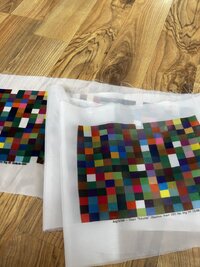
ThisHi Micronica: there is some cheating involved: I use photoshop to stretch and squeeze the whole thing for the patches to become square: this is not possible with printtarg only: you will end with elongated patches as always.
targen -v -d2 -g 16 -f 486 test
printtarg -r -v -i 22 -p A4 -a 1.2506 -T914.4 test
produces 486 x 10mm square patches on an A4 sheet:
The instrument type parameter seems to control the shape of the patches and peripheral annotations. The -a parameter scales the patch size. I didn't look at the output for other instrument types. There may be a more efficient option.
With the rule I printed I can read about 1 patch per second and about 5 seconds per column for rule alignment. So reading this would take just under 10 minutes.
This
targen -v -d2 -g 16 -f 216 testa5
printtarg.exe -r -v -i 22 -p 148.5x210 -a 1.2506 -T914.4 testa5
produces 216 10mm square patches on an A5 sheet.
The sheets need to be printed at 360 dpi. The -T parameter to printarg is supposed to set DPI (in tif terms resolution) but seems to need a value of dots per 2.54 inches to get dots per inch in the file.
Later: the -T parameter is OK at 360. Unusually Argyll sets a Resolution Unit tag in the file to a non-default cm and Qimage ignores that tag which led to the confusion. In Qimage I you need to override the set the resolution to 360 dpi.
Last edited: