Mod on Sudhaus Redsetter to use AA batteries

avolanche

Print Addict
Joined
Jun 5, 2007
Messages
247
Reaction score
64
Points
178
Location
East Tennessee
I just did a simple mod on my Sudhaus Redsetter($20 on Ebay) so that it can use AA Alkaline batteries in place of the Mitsubishi CR2032 3V "coin" battery that it uses from the factory.I planned on getting a Radio Shack AA battery holder(2 AA = 3V),but I just cheaped out and made a simple holder from a small piece of PVC pipe,a small spring and some wire for leads to 2 alligator clips.The typical AA holders are cheap and easily available,so it's probably best to go that route.

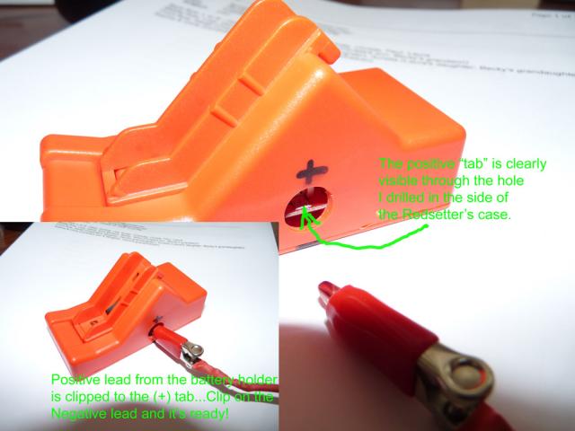
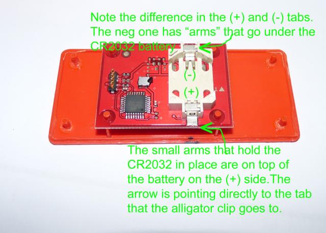
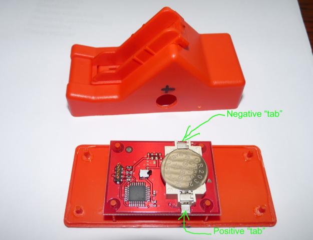
I took 2 alligator clips and soldered them to the leads of the battery holder.Then I drilled 2 holes (one on each side of the Redsetter) to expose 2 small metal tabs that connect with the positive and negative battery holder on the Redsetter.The alligator clips go into the holes and clip on these "tabs" on the pc board.I clipped it on(after removing the coin battery!) and it worked perfectly.

Here is a link to a previous post by Aussieinker and his mod to use an AC/DC converter.The leads were soldered to the tabs in his mod,where mine clip on temporarily(I may make it permanent later,but with the alligator clips I can easily use CR2032 or AA batteries with no wired protruding from the Redsetter).

Works like a charm.I know some purchasers of the Sudhaus Redsetter had problems with CR2032 batteries not holding up well.Most everyone has access to AA alkalines(and they are cheap!),so this is an alternative to AC adaptors.Proceed at your own risk,but it's a simple concept.....especially if you look at this previous thread: http://www.nifty-stuff.com/forum/viewtopic.php?id=4347

2264_p1020548res.jpg

2264_p1020546res.jpg

2264_p1020543res.jpg
 

Tristin

Newbie to Printing
Joined
Mar 17, 2010
Messages
1
Reaction score
0
Points
6
I came across to the forum when I was looking for some information about the microsoft certifications but I really found it good by all means
 

jimdandyy

Newbie to Printing
Joined
Sep 16, 2020
Messages
3
Reaction score
2
Points
3
Printer Model
Canon MP610
Hello. I started to try this mod on my old Redsetter and realized the switch on the board was breaking. I've taken it off the board in the hopes of soldering to complete the circuits and just connect and disconnect a battery, as needed. But I can't figure out which way to solder. It looks like there are 4 contact points and I think there need to be 2 connections made, but I'm not sure which point gets soldered to which. Anyone have advice? Thank you.
 
Last edited:

PeterBJ

Printer VIP
Platinum Printer Member
Joined
Nov 27, 2010
Messages
5,055
Reaction score
4,896
Points
373
Location
Copenhagen Denmark
Printer Model
Canon MP990
I think I found the switch on Amazon. It is a single pole single throw momentary switch. The four soldering tabs are for providing a more stable mounting to the PCB. How about replacing the switch instead of modifying the Redsetter?

If you hold the switch with the lever pointing up I think the tabs on each side are connected in parallel.

Here is a scan of a PGI-520/CLI-521 Redsetter PCB, the PGI-5/CLI-8 version looks similar, click to enlarge:

Redsetter circuit board.jpg

And a close-up of the left side of the switch, click to enlarge:

Redsetter Switch 1a.jpg

And the right side of the switch, notice possibly "blind" soldering island, click to enlarge:

Redsetter Switch 2a.jpg

I have had problems with the switch in both an original Redsetter for PGI-5/CLI-8 cartridges and also with the switch in a Chinese almost carbon copy of the Redsetter. I tried spraying some contact cleaner into the switch, but I don't know if that worked. What worked and made the resetter functional again was raising the PCB slightly using insulating washers/spacers cut from cardboard and punched with a leather pair of pliers type punch. Click to enlarge:

Redsetter Spacers.jpg

I had one of the power hungry 1st gen. Redsetters, which I modified with a battery box for 2xAA. It lasted for maybe 10 years but the contact pins on the resetter had become bent and one broke when I tried to straighten them.

I wish you good luck with the repair and could you please report your results whether positive or negative?
 
Last edited:

jimdandyy

Newbie to Printing
Joined
Sep 16, 2020
Messages
3
Reaction score
2
Points
3
Printer Model
Canon MP610
Thank you, @PeterBJ.

At this point, my switch is done for. The "paddle" broke. Now, I'm trying to avoid spending more money on a possibly botched repair (well, I might botch it in any case, but I'd like to try without spending money). Are you saying that all four solder points are just for mounting, or that the single-pole probably completes the path between the 2 points on the left side?

It sounds like you think the right side has a mount-only point (the "island"), but maybe it would be fine to join L-to-L and R-to-R? I was wondering if it was top-to-top and bottom-to-bottom, because I'm completely stupid in this realm, and can't tell by looking at the board what completes the circuit.
 

PeterBJ

Printer VIP
Platinum Printer Member
Joined
Nov 27, 2010
Messages
5,055
Reaction score
4,896
Points
373
Location
Copenhagen Denmark
Printer Model
Canon MP990
I think I might be wrong about the switch, I noticed the Amazon switches look to only have two soldering lugs so they are not the proper type. I think the proper type might be a double pole single throw momentary switch. I tried figuring out the function of the switch using my DMM with continuity test function. The standard probes are much too clumsy, so I made a couple of finer probes using sewing needles for better measurements

I now found another possible configuration and connection of the switch, this is seen from above:

Redsetter Switch Connection.jpg


The "island" connected to terminal 1 of the switch is not "blind" but connected to B+ like terminal 3 and 4 also are. A single pole single throw momentary push button switch connected between terminal 1 and 2 should then be sufficient, I think.
 
Last edited:

PeterBJ

Printer VIP
Platinum Printer Member
Joined
Nov 27, 2010
Messages
5,055
Reaction score
4,896
Points
373
Location
Copenhagen Denmark
Printer Model
Canon MP990
If I compare my PGI-520/CLI-521 resetter board to the PGI-5/CLI-8 in the first post they are different. I compared it to my Chinese Copy Resetter for PGI-5/CLI-8 and apart from the colour they look identical. I checked the function of the switch with my DMM and it is the same connection as in the PGI-520/CLI-521 resetter, so my drawing should still be valid.

Redsetter Copy PCB.jpg
 

jimdandyy

Newbie to Printing
Joined
Sep 16, 2020
Messages
3
Reaction score
2
Points
3
Printer Model
Canon MP610
@PeterBJ, your answers go way beyond what I expected with my simple question. Thank you so much for the helpful responses.

Regards,

Josh
 
Top