3rd Edition.........29th October 2018
It's Precision by loosness:
Assemble the carriage assemblies, locate in frame, loosen bolts holding the bearings until the assembly slides smoothly, not exactly the "Best Practice" with respect to precision engineering - but if it works, don't knock it.
Again not sure if I agree with positioning of the X 'Limited Switch'. This will be modified!
Just had to remove X motor to reposition the drive wheel, the gear was too far in towards the motor thus not aligned with the belt. I had to remove the motor as the grub screws were below the level of the acrylic plate. George the gorilla did up the grub screws, so quite a challenge to release them.
Interesting aside, all the screws supplied are countersunk. Non of the plates are countersunk. If you do countersink the acrylic, the screws bottom out. Ho Ho Ho.
......................31st October [Halloween - a portent ?]
Anyway IT's Alive.............
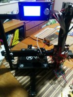
It has been a challenge. I followed the instructions on the supplied USB stick. Should have known better I suppose example;

Note the fixing plate is not the motor fixing plate but...

this image from later in the instructions (fitting the Z limit (sorry limited) switch) shows the same position as previous. The limit swith needs fitting on the motor plate side.
This caused quite a lot of headscrathing trying to get the home position working.
Still, there it is in all it's pre tidy up glory.

Note the Empty coffee cup lurking in the background. To Do hide the wires somewhere.
POST MORTEM.
It could have been worse.
Usually I worry if there are a few bits left over but in this case I just dont care. It works (at least it moves x,y,z and the LCD displays things..) I just need to get some filament now & see what happens. I thought they would supply at least a minimal amount to road test but nothing that looks like plastic... a few bits of wire, lots of screws, miscellaneous acrylic bits, a spare limitless switch but no filament.. ah well hello ebay.
Hints for new 3DP enthusiasts:
If the A2 is your first venture into mechanical assemblies, buy something else.
Make sure you have some decent tools - the ones supplied are questionable, for example the 1 spanner supplied will fit a 6mm nut, there is not one 6mm nut in the whole kit.
Check the quality / fit of supplied T nuts. Buy some decent ones if necessary.
Check all screws that secure items to the extrusion for length. If they bottom out then the unit being secured will not be tight to the extrusion thus causing misalignment.
Loosen all motor drive gears before fitting the belts. after fittingthe belt move the sliding bed backwards and forwards to align the gear on the motor. Now tighten the grub screws.
Z Axis. Leave the motor assemble loose on the extrusion. Secure the trapezoid rod into the motor's flex drive. Wind the rod into the brass screw (mounted on the X axis, turn the rod until the motor assembly is at a suitable level.
Pulll up the X axis to it's maximum travel. Give the Z motor assembly a shake as the screws are tightened into the T nuts. This ensures alignment of the Z axis.
Keep calm, have another coffee, don't give up. If I can do it (think I have anyway) so can you.
Cheers.




