You are using an out of date browser. It may not display this or other websites correctly.
You should upgrade or use an alternative browser.
You should upgrade or use an alternative browser.
Voltage outputs on K30290 PSU for MP-610
- Thread starter NickC
- Start date
- Joined
- Sep 10, 2007
- Messages
- 1,557
- Reaction score
- 1,424
- Points
- 293
- Location
- Laramie, Wyoming
- Printer Model
- Canon i960, Canon i9900
Goi here and translate (in google chrome).
http://www.elektroda.pl/rtvforum/topic2261357.html
You will see that this (and many) Canon power supplies need an "OK confirmation" from the printer to operate correctly. You cannot just remove the supply and start checking pin voltages...
Info also here (and marked plainly on supply).
http://azsurplus.com/index.php?main_page=product_info&products_id=656
Last edited:
- Thread starter
- #3
Unfortunately, from what I have read elsewhere those voltages printer on the power supply are not correct. A working one apparently outputs some quite different voltages. That is why I was hoping to find someone with a working one that they can test for me.Goi here and translate (in google chrome).
http://www.elektroda.pl/rtvforum/topic2261357.html
You will see that this (and many) Canon power supplies need an "OK confirmation" from the printer to operate correctly. You cannot just remove the supply and start checking pin voltages...
Info also here (and marked plainly on supply).
http://azsurplus.com/index.php?main_page=product_info&products_id=656
- Joined
- Sep 10, 2007
- Messages
- 1,557
- Reaction score
- 1,424
- Points
- 293
- Location
- Laramie, Wyoming
- Printer Model
- Canon i960, Canon i9900
Please include your reference of what else you have discovered about this matter. What did you read. What did it say.
- Joined
- Nov 27, 2010
- Messages
- 5,061
- Reaction score
- 4,908
- Points
- 373
- Location
- Copenhagen Denmark
- Printer Model
- Canon MP990
Schematic diagrams and other electronics info are rare in Canon service manuals, but the service manual for Canon Pixma 4200 has some electronics info. The power supply for the iP4200 has 3 output voltages: 16, 24 and 32 VDC, The output connector has 7 pins, one of them is for a control input from the logic board, as stated by turbguy.
Here is a table showing the pin out for the power supply connector on the logic board. As this connector is placed on the logic board inputs connect to outputs on the power supply, and the control output connects to the power supply control input.

Here is a picture of the logic board from a Pixma 4200. Note the presence of ferrite core inductors and electrolytic capacitors indicating the presence of voltage regulators for at least 5 VDC for USB and 3.3 VCD for sensors and logic in the printer. The power supply needs to have a standby mode supplying at least some voltage to the logic board, else the logic board cannot generate a control signal to start the power supply in normal operating mode.

So testing the power supply outside the printer will only show the lower standby voltage(s). A wild guess is that applying +3.3 V to the control pin and -3.3 V to one of the ground pins (which one?, the grounds might not be common) will start the power supply in operating mode. But beware, some switching mode power supplies can refuse to start or might even be ruined without a proper load.
The logic board drives the print head, among other things. At power up I think some test of the print head using the reduced voltage is done. If this test is passed the logic board sends an OK signal to the power supply. This explains why a defective print head can prevent the printer from powering up, and why sometimes after removing the print head the printer will start. A defective print head can also ruin the logic board, and a ruined logic board will most likely send no OK signal to the power supply.
So thanks to @turbguy for the electroda link that made me study the iP4200 service manual and figure out the interaction between the power supply and the logic board.
According to the druckerchannel.de forum Canon power supplies fail very rarely, instead failure to power up is caused by a defective print head and/or a defective logic board. I think this is very plausible.
If you want to study the schematics and tables, you find the iP4200 service manual here, and the MP610 service manual here, the MP610 manual doesn't have the electronics info, but might be handy in case of other errors. Before downloading the manuals from electrotanya, read this instruction.
Here is a table showing the pin out for the power supply connector on the logic board. As this connector is placed on the logic board inputs connect to outputs on the power supply, and the control output connects to the power supply control input.
Here is a picture of the logic board from a Pixma 4200. Note the presence of ferrite core inductors and electrolytic capacitors indicating the presence of voltage regulators for at least 5 VDC for USB and 3.3 VCD for sensors and logic in the printer. The power supply needs to have a standby mode supplying at least some voltage to the logic board, else the logic board cannot generate a control signal to start the power supply in normal operating mode.
So testing the power supply outside the printer will only show the lower standby voltage(s). A wild guess is that applying +3.3 V to the control pin and -3.3 V to one of the ground pins (which one?, the grounds might not be common) will start the power supply in operating mode. But beware, some switching mode power supplies can refuse to start or might even be ruined without a proper load.
The logic board drives the print head, among other things. At power up I think some test of the print head using the reduced voltage is done. If this test is passed the logic board sends an OK signal to the power supply. This explains why a defective print head can prevent the printer from powering up, and why sometimes after removing the print head the printer will start. A defective print head can also ruin the logic board, and a ruined logic board will most likely send no OK signal to the power supply.
So thanks to @turbguy for the electroda link that made me study the iP4200 service manual and figure out the interaction between the power supply and the logic board.
According to the druckerchannel.de forum Canon power supplies fail very rarely, instead failure to power up is caused by a defective print head and/or a defective logic board. I think this is very plausible.
If you want to study the schematics and tables, you find the iP4200 service manual here, and the MP610 service manual here, the MP610 manual doesn't have the electronics info, but might be handy in case of other errors. Before downloading the manuals from electrotanya, read this instruction.
- Joined
- Nov 27, 2010
- Messages
- 5,061
- Reaction score
- 4,908
- Points
- 373
- Location
- Copenhagen Denmark
- Printer Model
- Canon MP990
@NickC wrote:
Yes, read on:
By connecting a home made extension cable from the power supply output to the printer's power connector, I was able to measure the stand by and operating voltages and the control signal on a Canon MP610, that has a defective print head but still is able to turn on. I was also able to test both the standby and operating voltages with the power supply not connected to the printer.
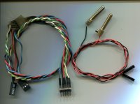
This is the extension cable and a cable to connect to a digital multimeter (DMM). The pin headers allow an easy voltage measurement and applying of a control voltage, click to enlarge:

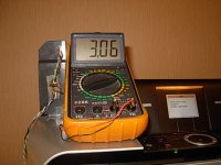
Here the extension cable is in use, click to enlarge:

The power connector has 5 pins. Starting from the top they are:
1. Control input, connects to the yellow wire. Voltage is 0 in standby and +3.06 V when powered on.
2. Ground, internally connected to pin no 4, connects to a black wire.
3. +7.48 V in standby, +24.0 V when powered on, connects to the red wire.
4. Ground, internally connected to pin no 2, connects to a black wire.
5. +9.75 V in standby, +31.8 V when powered on, connects to the blue wire.
These voltages were measured with the power supply connected to the printer. You can also test the power supply disconnected from the printer. Without any voltage applied to pin 1, you get the standby voltage of 7.48 V on pin 3, and a slightly higher standby voltage of 9.93 V on pin 5.
By applying +3.19 V from a small battery pack containing 2 alkaline AA cells to the control input pin, I got the same powered on voltages as above. The power supply did not blow up or fail by being started without a load.
If you want to test your power supply, I recommend making some adapter cable to avoid shorting the output pins with standard test probes.
The accuracy of the used DMM is specified as +/- 1% of reading and +/- 1 on the last digit, Ri = 10 Mohm.
Can anyone tell me what the voltages and approximate power requirements are on a K30290 PSU for a MP-610?
Yes, read on:
By connecting a home made extension cable from the power supply output to the printer's power connector, I was able to measure the stand by and operating voltages and the control signal on a Canon MP610, that has a defective print head but still is able to turn on. I was also able to test both the standby and operating voltages with the power supply not connected to the printer.
This is the extension cable and a cable to connect to a digital multimeter (DMM). The pin headers allow an easy voltage measurement and applying of a control voltage, click to enlarge:

Here the extension cable is in use, click to enlarge:

The power connector has 5 pins. Starting from the top they are:
1. Control input, connects to the yellow wire. Voltage is 0 in standby and +3.06 V when powered on.
2. Ground, internally connected to pin no 4, connects to a black wire.
3. +7.48 V in standby, +24.0 V when powered on, connects to the red wire.
4. Ground, internally connected to pin no 2, connects to a black wire.
5. +9.75 V in standby, +31.8 V when powered on, connects to the blue wire.
These voltages were measured with the power supply connected to the printer. You can also test the power supply disconnected from the printer. Without any voltage applied to pin 1, you get the standby voltage of 7.48 V on pin 3, and a slightly higher standby voltage of 9.93 V on pin 5.
By applying +3.19 V from a small battery pack containing 2 alkaline AA cells to the control input pin, I got the same powered on voltages as above. The power supply did not blow up or fail by being started without a load.
If you want to test your power supply, I recommend making some adapter cable to avoid shorting the output pins with standard test probes.
The accuracy of the used DMM is specified as +/- 1% of reading and +/- 1 on the last digit, Ri = 10 Mohm.
Last edited:
- Joined
- Sep 10, 2007
- Messages
- 1,557
- Reaction score
- 1,424
- Points
- 293
- Location
- Laramie, Wyoming
- Printer Model
- Canon i960, Canon i9900
Looks like what's embossed on the PS is correct, no?
- Joined
- Nov 27, 2010
- Messages
- 5,061
- Reaction score
- 4,908
- Points
- 373
- Location
- Copenhagen Denmark
- Printer Model
- Canon MP990
Yes, 100% correct, my power supply looks exactly like the one from the azsurplus link. Same type number and same data:Looks like what's embossed on the PS is correct, no?
Input: 100-240 VAC 50/60 Hz @ 0.89 A. Output: 24 VDC @ 0.5A and 32VDC @ 0.85 A.
The voltages I measured are within the specs, considering the tolerance on my multimeter.
Last edited:
- Thread starter
- #9
wrote:
Yes, read on:
By connecting a home made extension cable from the power supply output to the printer's power connector, I was able to measure the stand by and operating voltages and the control signal on a Canon MP610, that has a defective print head but still is able to turn on. I was also able to test both the standby and operating voltages with the power supply not connected to the printer.
.....
Thank you very much PeterBJ, fantastic info. As both of my power supplys are now outputting 0 volts maybe I should try to make an external PSU. If I get something outputting 24V and 32V do you think that might work or do you think the printer will need something on the 3v yellow wire as well.
- Joined
- Nov 27, 2010
- Messages
- 5,061
- Reaction score
- 4,908
- Points
- 373
- Location
- Copenhagen Denmark
- Printer Model
- Canon MP990
I wonder why you have two seemingly dead power supplies? With the power supply connected to the mains and without anything connected to the output connector, you should be able to measure the stand by voltages, around +7.5 V on pin 3 and around +10 V on pin 5 with pin 4 as the ground. No voltage should be present on pin 1 with pin 2 or pin 4 as ground.
I don't know if the power supply has an over current protection built in or it relies on the control signal from the logic board to shut it down in case of a malfunction? If the power supply has no over current protection of its own a short between pins 3 and 4 or 4 and 5 could ruin the power supply or blow an internal fuse.
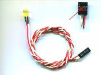
This risk is why I suggested to make a special cable for the testing , normal test leads are too big and clumsy for this purpose IMO. Front panel control lights and switches from an old PC are a good source of connectors that fit the power output pins on the power supply. These connectors come in at least 1, 2, 3, and 4 pole varieties. The wires can be removed from the connectors by lifting a plastic tab marked with an arrow, so you can make customized test cables. Click to enlarge:

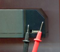
Here is a scan of the power supply and my standard test pins for the multimeter. It is seen that there is a great risk of creating a short during a measurement. Click to enlarge:

I think building a new power supply would be no simple task, as both the 24 and 32 V supplies must be able to supply the lower stand by voltages with no control signal on the yellow control wire and toggle to the operating voltages when a control signal is present. And are current limiting necessary and are the current limits the same in stand by and operating modes?
If the logic board is not already damaged then applying the higher operating voltages instead of the lower standby voltages before asked for might damage the logic board.
If you want to build your own power supply, no voltage should be applied to the yellow wire. Instead the voltage on this wire should be detected and used to control the power supply.
National Semiconductor makes a lot of voltage regulator IC's, both for linear and switch mode power supplies. So maybe ideas could be found in some of their data sheets and application notes? Some of these are available for download.
If errors made during the voltage measurement didn't ruin the power supplies then the printers logic board might be responsible, meaning that the printer is a total loss.
I don't know if the power supply has an over current protection built in or it relies on the control signal from the logic board to shut it down in case of a malfunction? If the power supply has no over current protection of its own a short between pins 3 and 4 or 4 and 5 could ruin the power supply or blow an internal fuse.
This risk is why I suggested to make a special cable for the testing , normal test leads are too big and clumsy for this purpose IMO. Front panel control lights and switches from an old PC are a good source of connectors that fit the power output pins on the power supply. These connectors come in at least 1, 2, 3, and 4 pole varieties. The wires can be removed from the connectors by lifting a plastic tab marked with an arrow, so you can make customized test cables. Click to enlarge:

Here is a scan of the power supply and my standard test pins for the multimeter. It is seen that there is a great risk of creating a short during a measurement. Click to enlarge:

I think building a new power supply would be no simple task, as both the 24 and 32 V supplies must be able to supply the lower stand by voltages with no control signal on the yellow control wire and toggle to the operating voltages when a control signal is present. And are current limiting necessary and are the current limits the same in stand by and operating modes?
If the logic board is not already damaged then applying the higher operating voltages instead of the lower standby voltages before asked for might damage the logic board.
If you want to build your own power supply, no voltage should be applied to the yellow wire. Instead the voltage on this wire should be detected and used to control the power supply.
National Semiconductor makes a lot of voltage regulator IC's, both for linear and switch mode power supplies. So maybe ideas could be found in some of their data sheets and application notes? Some of these are available for download.
If errors made during the voltage measurement didn't ruin the power supplies then the printers logic board might be responsible, meaning that the printer is a total loss.
Last edited:
Latest posts
-
-
-
-
-
ArgyllCMS profiles: Black Point Compensation gives composite black when checked
- Latest: Ink stained Fingers
