CLI-8 Cartridges, How does the chip really monitor ink?

canonfodder

Printer Guru
Joined
Sep 24, 2006
Messages
267
Reaction score
1
Points
109
Location
New Hampshire, USA
This may be a FNO message.

In the search for more understanding of Canon's chipped CLI-8 cartridges, I wonder if anyone has considered just how the ink information is really managed. Knowing the whole story could be very interesting.

It has been suggested that the count of ink jet commands is used to total up the amount that would indicate the ink level. This seems like a very reasonable assumption, but has anyone really checked this out. Does Canon suggest that, or do they say so directly in some publication?

The count of ink jet commands related to a specific cartridge would need to be stored in the chip.
Well, ..........not necessarily.

The ink level appears to be related to the specific, individual, cartridge. That being true means that the chip has a unique identity. A part of its identity is the ink color information to enable the 'wrong cartridge' function. Another part is EITHER a sort of serial number OR the ink level. A serial number could be set at the factory, even back at the wafer fab. Consider what a serial number can be used for. If the printer takes in the serial number, it can then total up the quantity of ink jets commanded for that chip/cartridge, keeping track of the information within the printer. This could mean that the chip does not have to be able to store this information. It would be required for the printer to have some non-volatile memory to keep the information. For the chip to be able to do its own record keeping, it would have to include some non-volatile memory.

There is a possible way to learn whether the chip really carries the ink level information or not. If a cartridge which indicates partly full were moved to a different printer, what would the ink monitor report? If it reports the correct partly full, then the chip must know the ink level. If the second printer thinks the cartridge is full, then it could be because the second printer has not seen that cartridge before, and assumes it is new and full.

Presently I am betting that the chip does keep count, meaning it has a non-volatile memory, but it would be very enlightening to learn that it does not. New avenues to deal with the chip would be opened.

Who on the forum could try this out for us? Move a partially full genuine Canon CLI-8 to another compatible printer and check the ink monitor's report.

Any volunteers ?
 

ghwellsjr

Printer Master
Platinum Printer Member
Joined
Jun 16, 2006
Messages
3,645
Reaction score
85
Points
233
Location
La Verne, California
Printer Model
Epson WP-4530
I don't know whether the method used for non-chipped cartridges (BCI-6) has any bearing on what is used for the chipped cartridges (CLI-8) but the ink levels for them is kept in the printer. No matter how many times you swap cartridges or just remove and replace, the printer has no way of knowing that you have done this. Eventually, it thinks you have used half your ink in a particular cartridge, and indicates that on the ink level display (if your printer has one). As long as you never insert an empty cartridge or allow a cartridge to go empty while in the printer, it will continue to show it half full. Even if you put a full cartridge in the printer, it will still show it half full. But if you put an empty one in and it detects it as empty and then put a non-empty one in (no matter how much ink it really has) it will show full and start counting down to half full again.

So this suggests some other tests that could be performed on just a single printer but they take a much longer time. Assuming that one of the new printers has an ink level display, when a cartridge gets down to half empty, replace it with a new one that is full. If the printer detects that it is full, then we know that the cartridge is keeping track of its own ink level. Also, you could continue to use this new cartridge (whether or not it detected it as full) until it registers empty. Then put back in the half full cartridge that was taken out earlier and see whether it registers as full or half full. This would tell you whether the new printers use the information from the prism to determine the condition of OEM cartridges.

Of course anyone trying these experiments takes the risk of having the printer reject an OEM cartridge that is not yet empty.
 

canonfodder

Printer Guru
Joined
Sep 24, 2006
Messages
267
Reaction score
1
Points
109
Location
New Hampshire, USA
ghwellsjr said:
So this suggests some other tests that could be performed on just a single printer but they take a much longer time. Assuming that one of the new printers has an ink level display, when a cartridge gets down to half empty, replace it with a new one that is full. If the printer detects that it is full, then we know that the cartridge is keeping track of its own ink level.
Not necessarily so. I wrote before:

"If the printer takes in the serial number, it can then total up the quantity of ink jets commanded for that chip/cartridge, keeping track of the information within the printer. This could mean that the chip does not have to be able to store this information." The serial number I refer to is one unique to the chip/cartridge.

Should the function be one where the printer takes in the serial number, a "new" cartridge can be just one that the printer has not seen before. If you are testing with a single printer, a new cartridge can be "new" and "full" to the printer because it has not seen it before, or "full" because the cartridge chip can actually report it full. So we can't tell which condition exists.
 

websnail

Printer VIP
Platinum Printer Member
Joined
Oct 27, 2005
Messages
3,661
Reaction score
1,345
Points
337
Location
South Yorks, UK
Printer Model
Epson, Canon, HP... A "few"
canonfodder said:
In the search for more understanding of Canon's chipped CLI-8 cartridges, I wonder if anyone has considered just how the ink information is really managed. Knowing the whole story could be very interesting.
There's a LOT of information out there but nobody has quite had the time or the printers available to them to try and check things properly but if you want you could easily pick up a few refurb printers yourself and a variety of Canon carts in them for a few hundred and test the theory yourself.

Appreciate that may sound a little harsh but the problem is that there seems to be some disparity between reported problems to date which makes life hard to start... And more importantly the time and cost involved in actually taking a proper look at the problem would run into weeks and more than a few hundred quid in consumables before one semi-complete answer could be found.

What I suspect would work a real treat is if someone could physically disassemble one of the chips and take a look at the actual hardware to see if there's any flashROM or RAM on the chip. That would answer a lot of questions right off the bat..
 

Grandad35

Printer Master
Platinum Printer Member
Joined
Feb 24, 2005
Messages
1,669
Reaction score
182
Points
223
Location
North of Boston, USA
Printer Model
Canon i9900 (plus 5 spares)
This thread also relies on some information in this thread (http://www.nifty-stuff.com/forum/viewtopic.php?id=1225). There seems to be a renewed interest in this subject, so here are a few more ideas to consider.

FNO Warning (For Nerds Only). I apologize in advance for the length of htis post.
Even though I don't have a printer that uses Canon's chipped cartridges, it presents an interesting challenge. There is nothing like being told that something is impossible to make an engineer try to figure out a way around the problem.

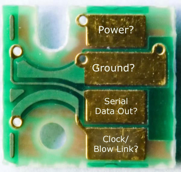
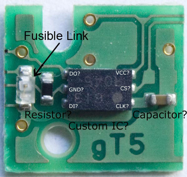
This morning, I purchased a CLI-8 cart (cyan) and removed the chip to see what it looked like. The "chip" is a two layer printed circuit board about 8 mm square by about 0.5 mm thick. This also gave me a chance to practice some macro photography, and here are the results - the notes on these photos will be discussed below. Note that the photo of the side with the 4 gold contacts is "flipped", so that it lines up with what is on the component side. The 5 gold holes are "vias" that connect the etch on the two sides of the printed circuit board - note that the 5 holes line up
CanonChip_ContactSideFlippe.jpg

CanonChip_ComponentSideM.jpg


The top photo shows the contact side that connects to the print head - clearly there are only 4 contacts. I am, of course, assuming that all of the carts have the same number of contacts. Could someone with one of these printers please confirm or deny this?

The bottom photo is far more interesting. I started by emailing it to someone who is familiar with current surface mount technology to get their opinion on what these components could be. I'm sure that there are others who are far more knowledgeable than I or he on this subject, so I encourage anyone who has either confirming or contradictory information to chime in. I think that I have already proven that I am not afraid to make wild conjectures in the hope of learning something, so don't be afraid of telling me that I am full of it - the important thing is that we advance our knowledge. Here is my list of SWAGs (Scientific Wild A**ed Guesses):
1. The color of the 2 lead component looks like it might be a capacitor. Note that Canon buys parts in such large quantities that they could obviously have parts specially colored if it suited their needs, but I'm relying on them using commercial components to save time and money.
2. The black device (above the "Resistor" note) is assumed to be a resistor. I should probably check its resistance, but it's only about 40 mils long (1 mm), and it takes a steadier hand and far finer points on the leads of an ohmmeter than I have to make this measurement. There is an additional reason for assuming that this is a resistor - see below.
3. The "Fusible link" has a very fine gold wire that is visible under high magnification, but which is less obvious in the photo. This device is the same size as fuses listed at (http://www.littelfuse.com/data/en/Product_Catalogs/Chapter10SurfaceMountFuses.pdf), and apparently confirms my previous conjecture about this design using a fusible link. Can someone who has a cart that registers "empty" pop the chip and look at this fuse under high magnification? The gold wire should be missing, like a blown fuse.
4. The IC appears to be a "6 Lead SOT-23" package with a size of 63 x 155 x 40 mils (width x length x thickness) (http://www.national.com/packaging/folders/mf06a.html)
5. This is pure conjecture, but the IC could be a serial eeprom (Electrically Erasable Programmable Read Only Memory). This link shows such a device and its pin out in this package on page 2 (http://ww1.microchip.com/downloads/en/DeviceDoc/21749F.pdf).
6. Using the preceding SWAGs, the appropriate signals were labeled on the IC and the gold contacts. Note that there are 6 traces that lead to dead ends at the edges of the PC board. It is another conjecture that these signals go to "testing pads" that allow the assembled device to be tested, but that these pads are then trimmed off after the assembly passes its Q/C check. These signals include: VCC, Ground, DO, Clock, CS, and the top end of the fuse. DI is apparently not tested (nor would it need to be, as the chip won't be programmed in place). Read below for a description of these signals.
7. Ground (GND - Pin 2) is connected to the two large areas of etch on the component side - it is a common practice to do this because it creates a "ground plane" to reduce electrical noise. One end of the capacitor would be connected to ground (the usual practice). It could not be verified that pin 2 of the IC was connected to ground because I would have had to destroy the IC to look under it. However, the circuit with the fuse and the resistor in series makes the most sense if the bottom end of the resistor was also connected to ground.
8. VCC (pin 6) goes directly to a contact, as would be expected.
9. The Data Out (DO) signal goes directly to a contact, as would be expected.
10. The Data In (DI) signal doesn't appear to be connected, but I would have to destroy the IC to verify this. If it isn't connected, the memory can't be changed in the printer, and this becomes a "Read Only" device. This conjecture is supported by the presence of the fuse - why would anyone add the complexity and cost of a fuse to record "cart empty" when they could just write some information to the chip and eliminate the fuse? Why wouldn't Canon just add a 5th contact to reprogram the memory? This is getting into conjecture based on conjecture, but it would allow them to claim that their device "could" be refilled by replacing the fuse. It could also be that this isn't really an eeprom at all, but a rom (Read Only Memory) that doesn't need a Data Input pin.
11. The CLK (Clock) pin signals the device when to transfer another bit of information. This signal has a capacitor to ground and also a resistor to ground when the fuse isnt blown. Depending on how this signal is generated by the printer, the frequency of the clock could be changed when the fuse was blown - data would still be sent, but at a slower/faster rate. This frequency could be sensed to let the printer know when the fuse was blown. It isn't at all clear how the fuse can be blown by the printer, since the "Clock/Blow Link" input would have to be pulsed with a high voltage to blow the link. The IC's input are only rated to withstand 1 volt below ground to 1 volt above VCC, but it is also rated to withstand 4,000 volts of an electrostatic discharge. This needs someone with far more knowledge that I to explain. If this is a custom IC, it wouldn't be a big problem to protect this input against a high voltage.
12. The CS (Chip Select) doesn't appear to be connected. The timing charts don't show and read cycles that don't use this signal, but there may be some special read sequence that is triggered when power is first applied to the chip. Even though there is no connection to the printer, this signal is connected to a test pad - go figure.

If your eyes aren't glazed over yet, here are a few more SWAGs about how this system could operate:
1. These chips are programmed (if they are eeproms) or fabricated (if they are roms) with a bit string that encodes the color of the cart and a unique serial number.
2. The printer can easily read each chip when the power is turned on, when a cart is changed, etc. This allows it to make sure that there is a cartridge of the correct color in each slot before printing.
3. As I explained in a previous post some older HP printers kept track of the ink usage by remembering the serial numbers of the last 2 carts installed in each slot, as well as the ink usage from each cart. With the availability of almost unlimited memory, each printer has the capability of remembering almost an unlimited number of serial numbers and the last known ink level for each serial number.
4. When a cart goes "empty", the printer blows the fuse to permanently mark the cart as either empty or refilled. Nags screens, etc. follow.
5. Even if the prism doesn't sense an empty cart (say, by covering the prism with black tape) a count of the ink drops will be used to trigger the "empty" signal and to blow the fuse.
6. When a non-empty cart is sensed with an unknown serial number and an intact fuse, it is assumed to be a new cart. If the fuse is blown, that serial number would also be flagged as empty by the printer.

It's time to think about yet another set of SWAGs - that Canon has been bluffing about the encoding and patents. Has anyone actually seen a Canon patent on this technology? If this system works as conjectured, there is nothing so novel about this system that they should be able to get a patent on it. Even if they did get a patent, the patent disclosure has to indicate how it works. I have read about "better encryption than nuclear missiles", but I don't see it. Even if they encrypt their data stream, all someone has to do is to read the data from several hundred carts to be able to sell several hundred unique chip sets to each user (since the printers don't talk to each other, each printer can see the same number and still think that it is unique). It is also possible that some form of date code may also be encoded into the data (like HP does), so everyone may get a surprise about outdated carts in a few years.

As far as the fuses are concerned, what would happen if they were replaced by a jumper? Do the printers check that the fuse is blown after they blow it? What do they do if it doesn't blow? It would be interesting to take an "empty" cart with a blown fuse, jumper it, refill the cart and try it in another printer. It should work, but what happens when it is time to blow the fuse in the second printer? I would only try this in a printer that I could afford to throw away if it burned something out until it was proven that it didn't cause any problems. If this worked, these "jumped" carts could be refilled by a large retailer and sold to other users on the basis that it would be unlikely that a user would get the same cart (serial number) back. Note that these carts would only have to be "jumped" once, so they could be marked as such. This could be a good business opportunity for someone.

As I have already stated, I don't have a dog in this hunt, so it is up to others to continue this work. Those who have potential business opportunities in this area have the resources and motivation to continue the investigation. I'm sure that the right person can open the IC and identify the technology involved.

I now have a perfectly good chip for a Cyan cart (actually, I have a complete Cyan CLI-8 cart), and I would be willing to trade the cart and chip for a few empty CLI-8 carts of different colors just to make sure that all of the chips have the same design and so that I can verify the pin connections under the IC. The first one to PM me can make the trade.

It's late and I'm tired (I'm sure that it shows in the writing). Please ignore the typos and spelling errors, as I'm too tired to give it a good proof read. Let me know what you think.
 

ghwellsjr

Printer Master
Platinum Printer Member
Joined
Jun 16, 2006
Messages
3,645
Reaction score
85
Points
233
Location
La Verne, California
Printer Model
Epson WP-4530
Grandad35 said:
I am, of course, assuming that all of the carts have the same number of contacts. Could someone with one of these printers please confirm or deny this?
I don't have one of these printers but I do have several cartridges that I got as extras when I bought some used BCI cartridges on eBay, including CYM PGBK and PM, and yes, all the chips look identical.

Grandad35 said:
I now have a perfectly good chip for a Cyan cart (actually, I have a complete Cyan CLI-8 cart), and I would be willing to trade the cart and chip for a few empty CLI-8 carts of different colors just to make sure that all of the chips have the same design and so that I can verify the pin connections under the IC. The first one to PM me can make the trade.
I don't know what "PM" means and I have no use for your Cyan cart but I will be happy to send you a Cyan, Magenta, and Pigment Black cartridge at no charge.
 

ghwellsjr

Printer Master
Platinum Printer Member
Joined
Jun 16, 2006
Messages
3,645
Reaction score
85
Points
233
Location
La Verne, California
Printer Model
Epson WP-4530
canonfodder said:
ghwellsjr said:
So this suggests some other tests that could be performed on just a single printer but they take a much longer time. Assuming that one of the new printers has an ink level display, when a cartridge gets down to half empty, replace it with a new one that is full. If the printer detects that it is full, then we know that the cartridge is keeping track of its own ink level.
Not necessarily so. I wrote before:

"If the printer takes in the serial number, it can then total up the quantity of ink jets commanded for that chip/cartridge, keeping track of the information within the printer. This could mean that the chip does not have to be able to store this information." The serial number I refer to is one unique to the chip/cartridge.

Should the function be one where the printer takes in the serial number, a "new" cartridge can be just one that the printer has not seen before. If you are testing with a single printer, a new cartridge can be "new" and "full" to the printer because it has not seen it before, or "full" because the cartridge chip can actually report it full. So we can't tell which condition exists.
I thought this issue was dealt with on this link where someone actually swapped cartridges from different printers:

http://www.nifty-stuff.com/forum/viewtopic.php?pid=8719#p8719

Has it been determined without any doubt that "The ink level appears to be related to the specific, individual, cartridge."? I was trying to offer another way to resolve that issue, not the issue of whether the printer or the cartridge or some combination associates the ink level with a specific cartridge.

It seems to me that Canon would not go to the extra work of keeping track of cartridges swapped before they are empty. They already have a mechanism in place for BCI-6 carts to determine ink level. Assuming a full cart, they count ink drops, report when the cart should be about half full and wait for the light detector to determine that the cartridge is empty. With the new chipped carts, when this happens, they blow the fuse. But as a backup, they continue to count drops until they know the cart should be empty and blow the fuse even if the light detector does not sense an empty cart.

Most users will not remove and reinsert a cartridge or swap a partially used cartridge with another one, either with more or less ink in it, until it is empty. As long as Canon never blows the fuse on a cartridge that still has ink in it, they will not get a legitimate complaint from a customer.

Now suppose the normal is happening. A cartridge runs dry and the printer blows the fuse. The user replaces it with another OEM cartridge that has an intact fuse and enough ink to cover the prism. Will the printer respond like the older printers and simply reset the ink level counter? I'm assuming this counter is in the printer and the cartridges do not have unique identities.

If this is the case, then a way to get around the problem caused by the chipped cartridges is to let your first set run dry and blow their fuses. Put in new OEM cartridges. The next time one of them reaches half empty, replace it with an empty cartridge with a blown fuse. Refill the half empty cartridge and put it back into the printer. Now the printer should report it as a full cartridge.

This will be fairly easy to test by anyone who has one of these printers and an empty cartridge of some color and a half full cartridge of the same color. Simply swap your half full cartridge with the empty one, see that the printer detects it as empty, then swap them again, and see if the printer detects it as full instead of half full. The worst that can happen is that the printer is a lot smarter than I'm hoping and it blows the fuse on your half full cartridge.

I don't have one of these printers but I do have several empty cartridges. I think I will visit one of these printers in a store and try this little experiment myself.

I'll let you know what happens.
 

websnail

Printer VIP
Platinum Printer Member
Joined
Oct 27, 2005
Messages
3,661
Reaction score
1,345
Points
337
Location
South Yorks, UK
Printer Model
Epson, Canon, HP... A "few"
Ok... I think I followed the logic and the "fuse" thing has my mind racing at the possibilities here.

If I follow the logic to its final conclusion one possible way to avoid the "empty" issue is if the chip was to have its fuse replaced with a standard connection. Of course that may result in the chip frying completely if the pulse is a little on the powerful side but it's a thought.

Unfortunately I'm not up for tackling the tiny stuff noted here but if I get a change I'll see if I can confirm or deny the fuse hypothesis.. Does sound mighty interesting.


Oh and one more thing.. in terms of the encryption.. It's my understanding that one chip genius who tried to reverse engineer discovered that the chip seems to (I'm trying to remember this correctly so please excuse any mistakes) communicate on multiple encryption layers so it'll check in one encryption mode and get a response, then query in another and get a response.. it's not possible to just pre-program a few sets of possible responses.

Don't forget also that the chips are very small and fabrication has been noted as being very difficult at that scale.. Oh and final point, the chip is supposed to have a VERY high clock rate, something like 10 to 100 times faster than the Epson chips so that also adds to the complexity.

Of course this is all third or fourth hand so take with the large pile of salt.
 

pebe

Printer Guru
Joined
Nov 2, 2005
Messages
239
Reaction score
0
Points
129
Location
Scotland
Once again grandad is to be congratulated on providing a very comprehensive write-up. I have been forming my own views on this subject for some time but without a specimen to go on, they have been pure conjecture. What you have proposed makes very good sense, but there are a couple of things I cannot understand.

1. The device must be interactive because it must output data in response to an enquiry, yet no data input is shown connected.
2. The capacitor on the CLK would slow down the rise and fall times of the clock. This is undesirable because it would allow noise at the transition times to interfere with the clock operation.
3. The link to the data on fusible links shows the lowest rated at .125A and blowing in 5 seconds at 200% current. Its resistance is given as 4 ohms so it would require 8v at 250mA to blow it. I dont know if it would be feasible to blow it without popping the chip. However, its low resistance would put a short circuit on the clock line and prevent operation.
4. Is it possible that the ground plane connects to DI?, with DI and GND being reversed? That would put the link in series with the DI pin. I cannot see what purpose would be served by the resistor. One end appears to be connected to nothing although its difficult to see under the opaque white stuff.
5. If the connections are as you have shown, then is is possible that each chip is interrogated by switching on its supply at Vcc. It would then output its identity at DO. But how the fuse works or gets blown is a bit of a mystery.

The question remains, though, how does the chip store info about ink usage if it cannot be written to?

My own view is that something like this may happen. The chip is possibility a microcontroller such as the PIC series here. http://ww1.microchip.com/downloads/en/DeviceDoc/41239C.pdf
These have an internal clock and can take data in or out on a single pin if necessary.

The printers main micro would write that usage data to the chip after every print session. It is possible that when new the chip has 255 in one of its registers and this gets decremented every time a certain volume of ink is used. When it gets to zero the end is signalled.

The main micro would address each chip in turn by sending a string of bits. The chip would check that certain bits in the string matched what it had in memory, and if so would reply with its own string and the main micro would check for a match. The string would indicate the colour.

The main micro could send thousands of different strings to encrypt the message only a few correctly placed bits would matter. When the chip had sent its message it would then go into sleep mode for 2minutes. That would prevent someone going quickly through all the possible addresses when trying to crack then code. When the usage register had got to zero the chip would send no data.

Just my thoughts.
 

Grandad35

Printer Master
Platinum Printer Member
Joined
Feb 24, 2005
Messages
1,669
Reaction score
182
Points
223
Location
North of Boston, USA
Printer Model
Canon i9900 (plus 5 spares)
pebe said:
The device must be interactive because it must output data in response to an enquiry, yet no data input is shown connected.
Remember that this is all a SWAG, but suppose that it outputs its entire data when VCC is applied? You are correct that there is no external means to interrogate the chip, but you need VCC, GND a clock and a serial out - how do you get a signal in? This isn't a problem if the device is read only.

pebe said:
The capacitor on the CLK would slow down the rise and fall times of the clock. This is undesirable because it would allow noise at the transition times to interfere with the clock operation.
You are obviously correct, but some chips can handle a sloppy edge better than others (e.g. if it has a Schmidt trigger on the clock input), and burning out the fuse will remove the resistor from the circuit, altering the clock frequency if it is driven by a simple RC oscillator in the printer's driver.

pebe said:
The link to the data on fusible links shows the lowest rated at .125A and blowing in 5 seconds at 200% current. Its resistance is given as 4 ohms so it would require 8v at 250mA to blow it. I dont know if it would be feasible to blow it without popping the chip. However, its low resistance would put a short circuit on the clock line and prevent operation.
The link was given only to show the availability and size of commercial devices to do this function, not to suggest that one of these was the device used by Canon. I got an interesting PM (Private Message) this morning from someone saying that the "fuse" was actually the LED that signals that the cart is empty. This is a very good point - I forgot about the LED. However, I think that this device is actually both devices in one - a fuse with an LED across the fuse to indicate when the fuse has blown. To verify this, I would love to see what the chip from an empty cart looks like - if this is a fuse, the gold wire will be missing. Note that the fuse is connected in series with the resistor and then to ground, so it would not short circuit the clock, just load it with the R/C combination on the PC board. I also had an idea on how to blow the fuse - the clock could be a low duty cycle or run only in short bursts during normal operation, then switch on at 100% to blow the fuse.

pebe said:
Is it possible that the ground plane connects to DI?, with DI and GND being reversed? That would put the link in series with the DI pin. I cannot see what purpose would be served by the resistor. One end appears to be connected to nothing although its difficult to see under the opaque white stuff.
My SWAG is that the resistor is used as described above.

pebe said:
If the connections are as you have shown, then it is possible that each chip is interrogated by switching on its supply at Vcc. It would then output its identity at DO. But how the fuse works or gets blown is a bit of a mystery.
My guess is that it is interrogated exactly as you describe and that the fuse works as described above.

pebe said:
The question remains, though, how does the chip store info about ink usage if it cannot be written to?
My SWAG is that it doesn't - this information is stored in the printer's memory for the last (say) 10,000 carts (this would only take 4 bytes/cart).

pebe said:
My own view is that something like this may happen. The chip is possibility a microcontroller such as the PIC series here. http://ww1.microchip.com/downloads/en/DeviceDoc/41239C.pdf
These have an internal clock and can take data in or out on a single pin if necessary.
..
There is nothing to say that your concept isn't the correct one - I admit that mine is just a SWAG. The more ideas that are put forward and the more people that look at this, the sooner we will figure out how it works. If anyone wants a copy of the photos without my notes to post their own ideas, they are posted at:
http://www.nifty-stuff.com/img/files/CanonChip_ContactSide.jpg
http://www.nifty-stuff.com/img/files/CanonChip_ComponentSide.jpg

One point that I want to clarify in my hypothesis is that even if you replace the fuse, the printer that blew the fuse can still recognize that this cart was once empty by the serial number sent by the chip. It "should", however, be recognized as a new cart by any other printer that has not previously seen that serial number. I believe that my SWAG explains most of the factual reports that I have read. As always, the true test of a theory is how well it predicts things that have not yet been tested.

One final comment - there are two current threads on the same subject. Should these threads be merged? (Rob?)
 
Top