Clogged Canon print head

mikling

Printer VIP
Platinum Printer Member
Joined
Jul 2, 2006
Messages
3,239
Reaction score
1,471
Points
313
Location
Toronto, Canada
I have reason to believe that there are failure modes on the printheads that seem on the surface to be a "clog" to the casual observer. To the more experienced, they would point to kogation issues being disguised as a clog. While less frequent, there is also real physical wear within the printhead chamber and heaters and the nozzle opening itself and then the more insidious electrical/electronic failure.

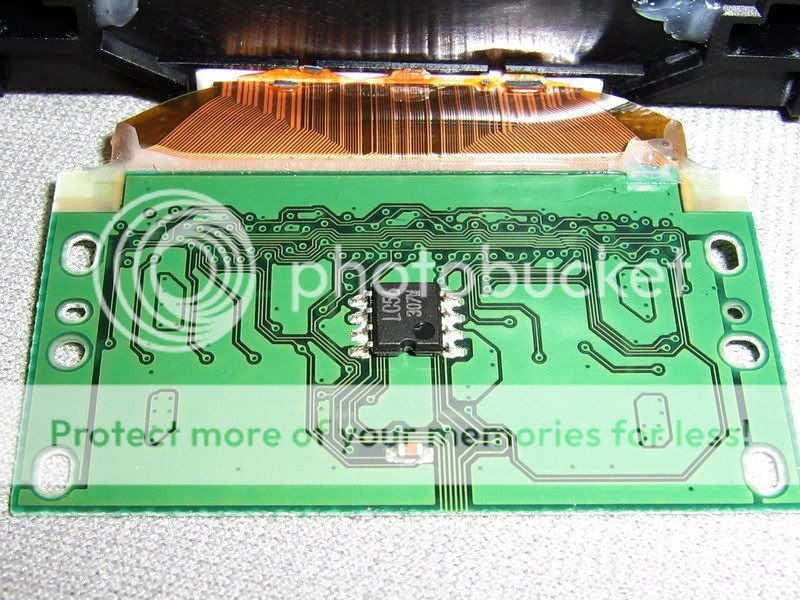
Canon heads must use an addressing system with a decoding IC on the rear of the contact board. I have seen one situation where the logic board had a failure in one of the address lines and it systematically destroyed each printhead that was inserted. Two heads were sacrificed. Worse yet, the faulty logic board did not indicate any failure. Only when the printheads were placed into another printer they were diagnosed as a faulty printhead.

As to proving it, it would be difficult and expensive unless you were given access to unlimited amounts of printheads like Canon R&D.

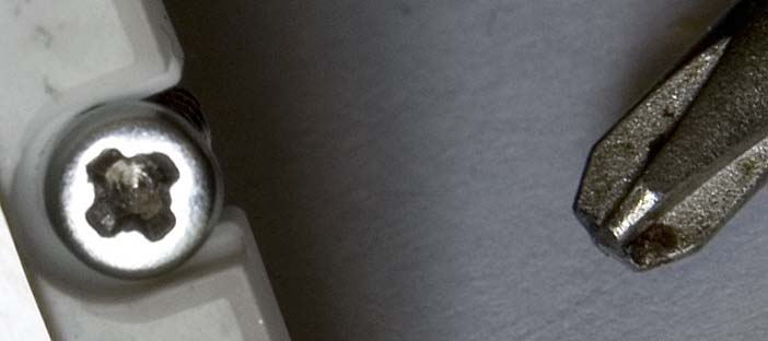
Here's something for you guys who have never seen inside one of these heads. They are quite simple heads physically until you get into the nozzle plate and that is where all the action is.

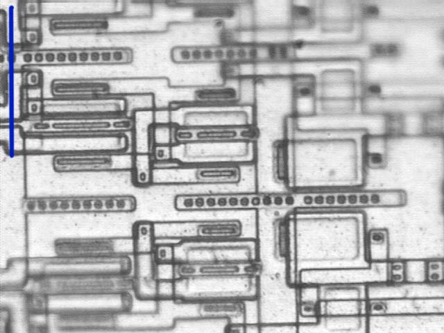
The IC that is behind the contact plate
HeadRearIC.jpg


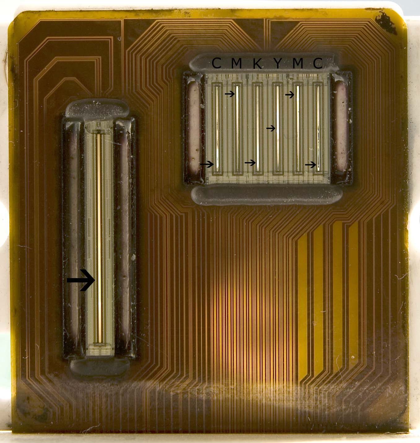
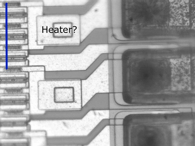
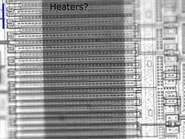
What's behind that nozzle plate/printhead plate?
HeadChannelsnotsealed.jpg


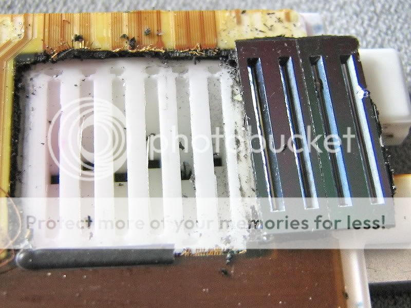
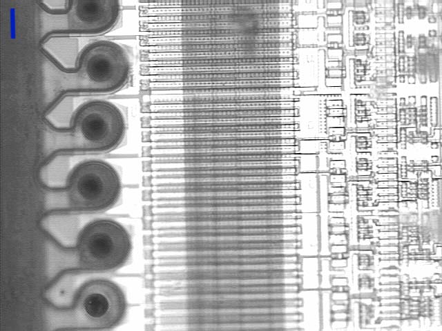
The 6 ink channels of the i950/960
Inkchannels.jpg


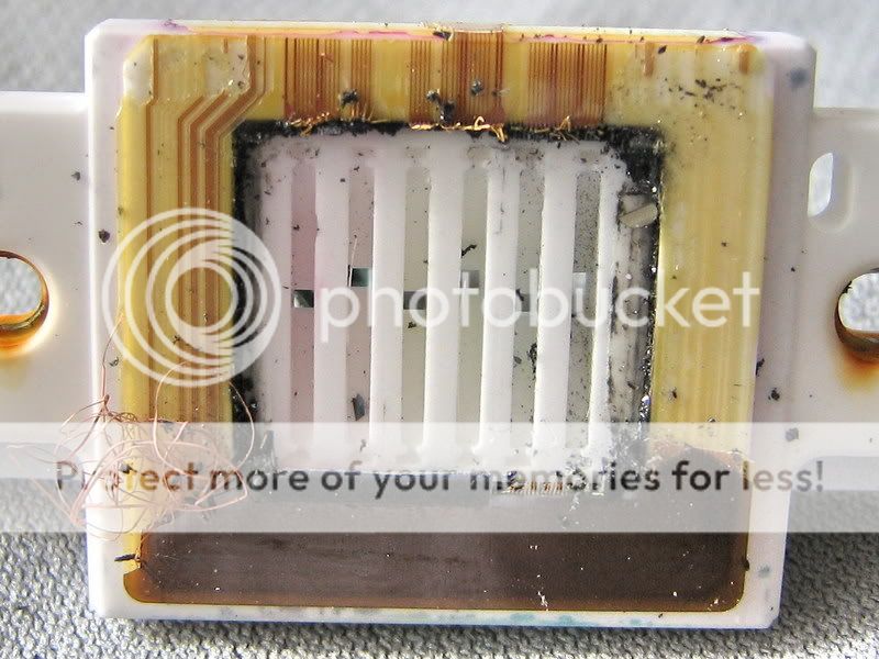
Notice the wells at the end of the ink channels, these are there to maintain a wicking action and ensure that the ink is there for the head even at the end through capillary forces. If the well runs dry, you can get bad ink feed issues at the ends. Note as well that the plate is all that seals all the separate ink colors. Sometimes the plate bonding goes bad and you get cross-contamination between the colors. I must admit though that when these were taken apart, there didn't seem to be any bonding. So I wonder if the surface tension of the ink and the small gap is all that prevent cross contamination. These pics are about a year old so my memory is a bit off.

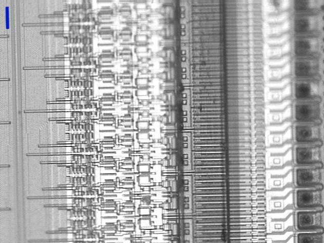
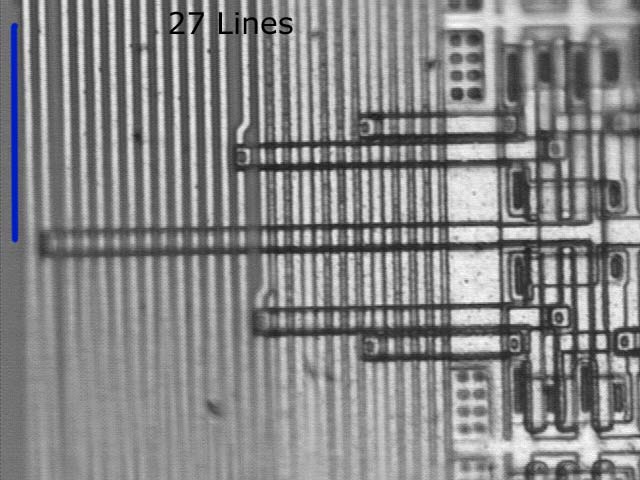
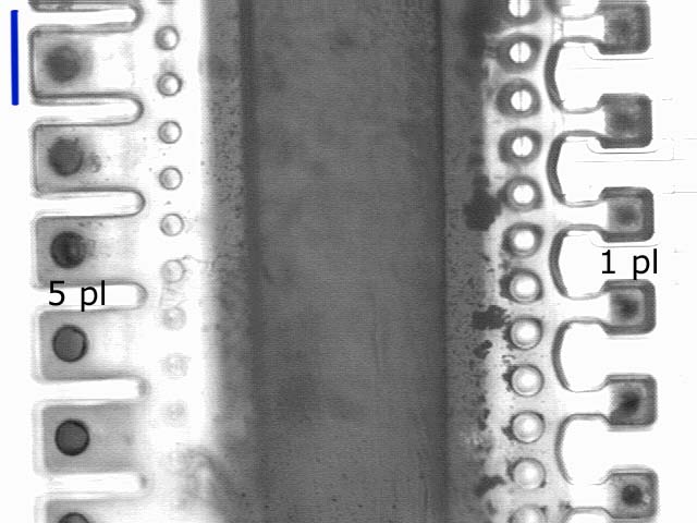
Pay attention to this, this head has 3,072 nozzles with equal amounts to each of the six colors in this head. Look carefully at the wires, there aren't 3,072 / 2 wires. Maybe someone can figure out the decoding addressing by counting the lines but it seems to me that there might be more decoding going on at the nozzle plate or maybe each nozzle is actually not separately addressed! but shoot in groups! Now this would explain a lot as to how Epson gets away with much fewer nozzles yet can retain an equally smooth gradation.

All just speculation above but interesting nonetheless.
 

ltsang

Getting Fingers Dirty
Joined
Mar 16, 2007
Messages
73
Reaction score
0
Points
34
Hi everybody,
I spend quite a bit of time looking at this particular topic tonight, it is sure interesting to see so many replies in one day that I have to throw in my 2 bits.
I like to print pictures but don't like fixing printers. I refill all my cartridges so I can print cheap. As far as clogged print heads, for canons, I put the ph under the tap and flush with warm tap water. Do 1 or 2 head cleanings and that is all I would spend my time on the printer. If still cannot fix the problem, time for a new one. Thats why I ended up with so many old printers, but they are all still working units. I stick to buying only printers, not 3 in 1's or fancy printers with a useless led screen. My last Canon cost me $60 and got a new set of oem cartridges which alone worth $80. I tried to fix an plugged Epson last week and ended up tearing it apart to get to the power supply. Printers nowadays are made to be disposed, not fixing. Sounds I am causing a lot of environment problems but I would spend my time doing things more fun, Grandad will probably disagree with me. People will fix a Rolex but not some cheap $10 watches.
Went to a friend to see his 10 ft long Epson printer (plotter) that uses ink cartridge cost $100 for one color. He has to soak the print head in some kind of cleaner supplied by Epson every night. So expensive printers have head clogging problems too. BTY, you can clean your print head any way you want but never try it in an ultrasonic cleaner, the print head will get fried in no time. I learned it when I was playing around with BC20 cartridges. Have fun my friends.
 

ghwellsjr

Printer Master
Platinum Printer Member
Joined
Jun 16, 2006
Messages
3,645
Reaction score
85
Points
233
Location
La Verne, California
Printer Model
Epson WP-4530
I don't think counting wires will tell you anything because there are tons more electronics surrounding the nozzles. Take a look at the picture in this thread of the closeup of the bottom side of a print head:

http://www.nifty-stuff.com/forum/viewtopic.php?id=1504

It seems pretty obvious to me that if a nozzle check shows one half of the nozzles consistenty not working that that would indicate a defect in the electronics in the part surrounding the nozzles which would be impossible to fix.

Also, we know that each individual nozzle can fire independently of all the others because that is what happens during a nozzle check.
 

mikling

Printer VIP
Platinum Printer Member
Joined
Jul 2, 2006
Messages
3,239
Reaction score
1,471
Points
313
Location
Toronto, Canada
Yes, I guess all the action is where the nozzles are. Lots of decoding and addressing right at the nozzle plate.
Here's an example a "real burnt out" head, the whole nozzle seemed like it exploded or burnt out. What is interesting is that this head did not register a 7 flash indication despite it's obvious damage. Odd huh?
BurntOutHead-1.jpg
 

Grandad35

Printer Master
Platinum Printer Member
Joined
Feb 24, 2005
Messages
1,669
Reaction score
182
Points
223
Location
North of Boston, USA
Printer Model
Canon i9900 (plus 5 spares)
mikling, ghwellsjr,

Great information and images. A few observations and comments:
1. Your photo shows that both banks of nozzles are fed from a single supply channel. There have been instances in the past where it has been postulated that the loss of one of the two banks of nozzles could be caused by a clog in the ink channel feeding that bank; with this ink channel design, that failure mode isn't possible.
2. I have a different theory on the purpose of the wells at the end of each ink channel. My guess is that they contain a small air bubble, which is the reason for the constriction at each end - the constriction makes it difficult for an air bubble to escape. These air bubbles act as accumulators, allowing the nozzles to quickly recharge with ink after they fire. This explains one of the operating details that has always seemed to defy logic - how can the nozzles recharge so quickly if they have to pull the ink all the way from the cart? The answer is that they don't have to: these "bubble accumulators" allow the nozzles to almost instantly suck in a few picoliters of ink, forming a slight vacuum in the ink channels and allowing the ink to be slowly pulled in from the cart to replace the pulse of ink that was sucked into the nozzle. If lots of nozzles fire in a short time, the vacuum would be higher, and the ink flow from the carts would increase.
3. This post also shows that the ink dots aren't laid down in groups, further confirming that the nozzles are fired individually.
4. These various photos show that it is almost certain that most of the decoders and drivers are spread out and located next to the nozzles. This makes sense, since the nozzles and heaters are probably laid down as part of a semiconductor fabrication process, so incorporating some additional logic and power traces wouldnt be a problem. Based on this knowledge, it is most likely that problems where complete sections of nozzles fail to print are caused by an electrical problem, not a "clog" in the traditional sense.
5. Your photo of a blown head shows that there is a LOT of power available to the nozzle heater drivers. Even though this much damage looks like what would happen if the power and ground lines were shorted together, it shows that a single failed heater driver has the potential to "take out" an entire bank of nozzle heaters by grounding or blowing open a single signal or power line. If just the heater itself failed, only one nozzle would be taken out. This nozzle check and this nozzle check fall into the category that would most likely be caused by this type of electrical failure.
6. It would be great if we knew that an electrical failure such as these examples show could be repaired by replacing the print head. However, as you said, more than one component can be involved, and a failure in the logic board can destroy replacement print heads. I also seem to remember seeing a post where a failed print head caused a failure in the logic board of a (previously) working printer. This doesn't answer the question of "What do I do when I get this type of nozzle check?", but perhaps others can chime in with their experience and we can generate some statistics on how often replacing the print head fixes this type of problem.
 

mikling

Printer VIP
Platinum Printer Member
Joined
Jul 2, 2006
Messages
3,239
Reaction score
1,471
Points
313
Location
Toronto, Canada
With the aging of the i9X0 line, I expect an increasing amount of problem printheads in the next couple of years. I was looking at the replacement cost of the heads as I am in that quandry and what struck me was that the heads for the i950/i960 are substantially more money than that of the iP6600/6700D. This has me stumped because the iP6600/6700 head is of a higher density and I would have expected a lower yield on the process for these heads as compared to that of the i950/960 or has Canon realized that many people would purchase replacement heads to avoid the chipped printer issue and would possibly pay more?


I wonder??????

Grandad

As to the ink wells, my theory is that they have to be filled with ink since the actual surface tension of the liquid is very high. This allows the well to literally pull/stretch the ink to the end. The constriction is there so that the nozzle firing cannot pull the last remaining ink in the well out thus insuring that the ink is always literally pulled to the ends. If it wasn't there, the ink would not make it to the end reliably. So what happens if air enters into the well? Well, with a head cleaning, or deep clean I theorize that there is enough vacuum to evacuate the well and then upon removal of the vacuum, the ink moves in to fill the void. In essence the process is analagous to a deep vacuum refill on integrated heads.
 

Grandad35

Printer Master
Platinum Printer Member
Joined
Feb 24, 2005
Messages
1,669
Reaction score
182
Points
223
Location
North of Boston, USA
Printer Model
Canon i9900 (plus 5 spares)
mikling said:
As to the ink wells, my theory is that they have to be filled with ink since the actual surface tension of the liquid is very high. This allows the well to literally pull/stretch the ink to the end. The constriction is there so that the nozzle firing cannot pull the last remaining ink in the well out thus insuring that the ink is always literally pulled to the ends. If it wasn't there, the ink would not make it to the end reliably. So what happens if air enters into the well? Well, with a head cleaning, or deep clean I theorize that there is enough vacuum to evacuate the well and then upon removal of the vacuum, the ink moves in to fill the void. In essence the process is analagous to a deep vacuum refill on integrated heads.
I'm afraid that this is just one of those cases where we'll have to agree to disagree, as there doesn't seem to be any practical way to see what really happens in these ink channels.
 

mikling

Printer VIP
Platinum Printer Member
Joined
Jul 2, 2006
Messages
3,239
Reaction score
1,471
Points
313
Location
Toronto, Canada
I wonder if Canon has any writeups or any patents on this inkwell. That might give some insight into how those little things work for sure. My theory is just speculative so I can be totally wrong.
 

Tin Ho

Print Addict
Joined
Apr 24, 2006
Messages
866
Reaction score
26
Points
163
You really want to know, as a printer owner, the fundamental difference between thermo bubble-jet (Canon, HP, Lexmark, etc.) and piezo-jet (Epson). If you own an Epson and if you buy poor quality refill ink the worst that could happen to you is to get a clog that can be unclogged if you know how. But if you own a Canon and if you refill with poor quality ink or use poor quality ink cartridges the worst that could happen is it may damage your print head.

To be more specific, if the ink or the ink cartrige is not feeding ink fast enough, or having an insufficient ink flow in another term, the heaters in the nozzles will not be cooled sufficiently. The ink will be really boiled and vaporized inside the nozzles. Guess what will happen when ink is vaproized inside the nozzles. This is really the most common cause of print head clogs among Canon printers.
 

Grandad35

Printer Master
Platinum Printer Member
Joined
Feb 24, 2005
Messages
1,669
Reaction score
182
Points
223
Location
North of Boston, USA
Printer Model
Canon i9900 (plus 5 spares)
This is a long "FNO" post.

In a previous thread, Zack23 reported a problem where multiple heads stopped printing "light magenta" on an ip5000. That printer is claimed to have both 1 pl and 5 pl nozzles on the magenta and cyan inks to get a similar effect to using "photo" magenta and cyan. Zack23 was kind enough to send one of his failed print heads for (destructive) analysis.

The ink was flushed from all channels using a syringe fitted with a drinking straw that fit over the ink pickup. It flushed easily, and there was no sign that any of the nozzle sets had a clog. The nozzle plate was removed as was described in the first post in this thread. The screws in this print head were difficult to remove, as the 4 point drive did not fit a conventional Phillips screwdriver very well. This was solved by grinding off the tip of an old screwdriver so that better engagement was achieved - see below:

In all of these images, only a thumbnail appears. Click on the thumbnail to get a bigger image. A few of the large images are downsized to fit on the screen, and the full width version can be seen by clicking again on the full sized image.

There are 42 contact pads on the back of the PC board connected to the nozzle plate, but there are 92 lines leading from the PC board to the nozzle plate (this shows a small section of the cable with enough detail to count the signal lines.

The small IC on the PC board only has 8 legs, so that can't explain the extra signal lines. I wonder if the IC isn't a small controller that reads the temperature at several places on the nozzle plate? Could they just be running duplicate lines for each signal so that a failure on one line wouldn't disable the print head?
Edit - this part is marked "S93C56", which appears to be a 2048 bit serial EEPROM.

The flexible cable is apparently attached to the bottom of the nozzle plate, as can be seen with a strong back-light (the nozzle plate is slightly translucent under a strong light). There are 6 sets of nozzles for the dye inks (as noted on the photo), with 2 sets for magenta and cyan. Yellow and black have only 1 set. The strong back light showed a bright area (as noted by the small arrows) directly in line with the holes in the back of the nozzle plate where the ink feeds into each set of nozzles.

The pigment black nozzle apparently gets 20 signal/power lines and the dye based smaller nozzles get 73 signal/power lines (1 line is connected to both).

The next several images are photomicrographs captured from a video camera mounted on a microscope. Microscopes have a very shallow DOF (depth of field), and it is not uncommon for one area on an image to be in focus with other areas out of focus, especially if the two areas are not at exactly the same height. In this case, the logic is at different levels (especially from the nozzles), so please forgive the lack of focus on some areas. Because the photomicrographs were taken at several magnifications, a vertical blue bar is included on the top left of each image, and this bar is 1/600 inch high (the spacing between nozzles on the dye inks).

As we had previously conjectured, there is a LOT of logic on the nozzle plate. This image was taken in the "common area" at the top of the dye ink nozzle plates.


This image starts with the decoding logic on the left and ends with the nozzles on the right.


This is a 5x larger magnification of the area on the left, showing how the signals for two nozzles are picked off of 27 vertical lines (other nozzle sets look the same, but they attach to different lines).


This shot was taken a little further to the right, and shows some of the decoding logic/power transistors.


This is a close-up of a few nozzles on the right and what I believe to be the heaters that boil the ink just to their left. Each nozzle has a duplicate device located in the same relative position. This design is consistent with a "side shooter" nozzle, as used by Canon.


This image shows a surprising result - the 5 pl and 1 pl nozzles are located side-by-side in the same bank of nozzles. There are two duplicate nozzles sets for magenta and cyan, giving 256 large and 256 small nozzles for each color. I guess that this makes sense, since it keeps the same ink flow in each channel. The "heaters" are the same size for both sets of nozzles. Note that the 1 pl nozzles are located between the 5 pl nozzles.


This shows the pigment black nozzles. They are spaced at 1/300 inch compared to 1/600 inch for the dye nozzles. This nozzle set is about 2.5x as long as the dye sets, so there are about 320 pigment black nozzles instead of 256. They appear to have a larger diameter, but I couldn't find any information on the drop size for these nozzles. One big difference between the pigment and dye nozzles is in the size of the heaters (assuming that that's what they are) next to each nozzle. These devices occupy the same relative space as the smaller heaters for the dye nozzles.


This is a close-up of a few heaters - they are huge compared to the dye heaters.


Given Zack23's problem with this print head, I spent about 30 minutes looking at all areas of the nozzle plate to see if there was any evidence of a blown circuit. There was no evidence of even a minor failure, much less anything like that posted by mikling,

Up to this point, the testing has been non-destructive. The plan is to start cutting and grinding next week.
 
Top